
Trusted Firmware 是 ARM 基於自家具有 TrustZone 功能的處理器所實作的開源程式,其主要目的是讓相關廠商可以更快速地將 TrustZone 架構性的整合到產品當中,此外同時也是廠商要取得 ARM PSA certification 認證的參考資源。由於近年來資安議題逐漸受到重視,愈來愈多客戶開始尋找結合硬體實現的安全方案,因此就有這個機會了解一下 Trusted Firmware 軟體架構及其中的 secure boot 流程。Trusted Firmware 包含了幾個專案,這篇文章是以其中的 Trusted Firmware-M(Arm v7-M & v8-M) 為例,如果是 A 系列的處理器則有 Trusted Firmware-A 可供參考。
Overview
首先先來看 Trusted Firmware-M 的架構:
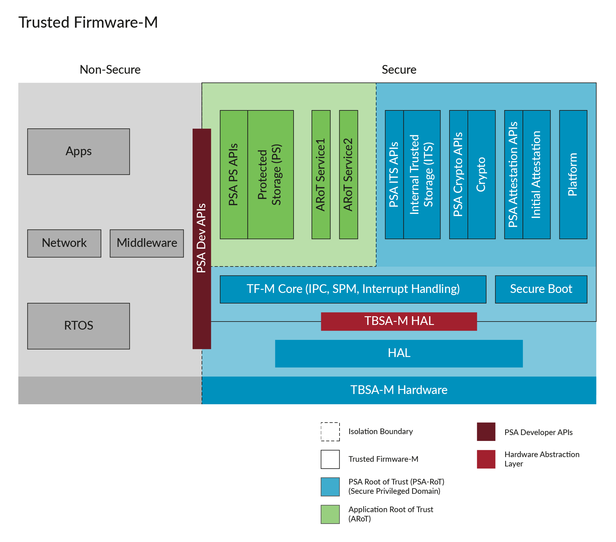 image resource: developer.arm.com
最主要的概念是透過硬體控制 (記憶體位置區間、權限控管等)的方式,將原先的執行環境切割成 secure processing enviroment(SPE) 和 non secure processing enviroment(NSPE) 兩個執行環境。SPE 主要是提供需要安全保護的服務,例如韌體更新、加解密;而 NSPE 則是一般使用者執行應用程式的環境。如果在 NSPE 中執行的應用程式使用到 secure 層級的服務,則需要透過特定 API 來呼叫(這個概念類似作業系統的 user-space 和 kernel-space 會透過 system call 來溝通),這樣可以限制 NSPE 的操作權限,避免重要機密資源外洩。
聽起來有點抽象,那就來舉個具體的例子吧!
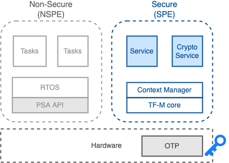
假設有一個應用場景是:一個應用程式需要使用硬體所保護的 OTP(one-time programmable) secure key 來進行資料的加解密。
執行流程就會是:
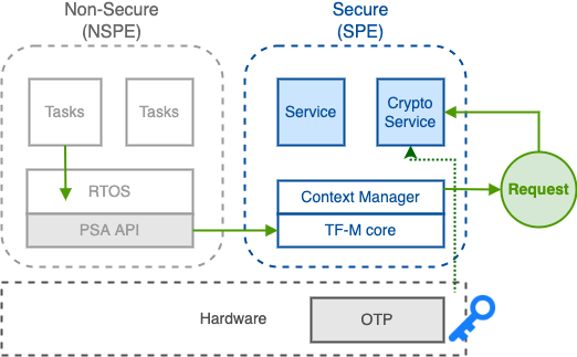
- Task(應用程式) 呼叫整合進 RTOS 的 Crypto PSA (Platform Security Architecture) API,發出 Crypto request。
- TF-M core 收到 request,由 context manager 產生對應的 request context (包含執行此 request 的 stack、crypto service ID 等)。
- Crypto Service 接收到此 request,接著呼叫 hardware API 從 OTP 讀取 secure key 並進行加解密演算法。
- 加解密完成,Crypto Service 將加解密後的結果透過 context 回傳給 Task。
如上述例子,由於重要的資料或是 key 僅能在 SPE 下存取,因此透過此架構來處理加解密需求,就能確保在 NSPE 執行的應用程式不會取得 key。
Secure Boot
除了 NSPE 和 SPE 兩個環境的溝通流程之外,secure boot 也是 Trusted Firmware 很重要的設計環節。Secure boot 最主要的目的就是防止系統使用到惡意的韌體程式或作業系統,在開機流程中,boot code 會先透過密碼學 (cryptography) 演算法驗證是否為可信任的的程式,如果驗證成功即會開始執行,否則中止流程。
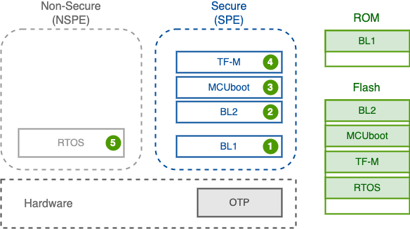
在 Trusted Firmware-M 的 secure boot 流程如下:
-
Boot loader stage 1 (BL1)
- 此階段主要是必要的硬體初始化或是設定,因此 BL1 boot code 必須要是可信任且不可被竄改。在執行完初始化後,就會跳到 BL2 的 entry point 繼續執行 BL2。
The bootloader code must be stored and executed from ROM or such part of flash memory which supports write protection.
-
Boot loader stage 2 (BL2)
- BL2 負責其他需要的初始化操作,例如啟動 MCUboot 前所需的設定或檢查,接著就會把執行移交給 MCUboot。
-
MCUboot
- MCUboot 是針對 32-bit microcontroller 所設計的 secure bootloader,其中包含完整的程式驗證流程,因此也是 Trusted Firmware-M secure boot 流程的核心。而 MCUboot 本身是獨立的 open source project,因此也能應用在其他專案上。
-
TF-M
- TF-M 會依據 memory layout 放置在指定的記憶體位置,而 MCUboot 會先去該位置取得 TF-M binary code,並且進行相關驗證確認,如果 TF-M 已被加密,也會在這階段進行解密。在確認完 TF-M 是正確且可信任後,就會載入 TF-M。要注意的是,Trusted Firmware-M 手冊中有提到,驗證和解密所需 key 建議放在 OTP memory 中,以確保不可修改。
ROTPK (root of trust public key) can be stored in a one-time-programmable (OTP) memory.
- 此外,由於需要在載入 TF-M 前就對 TF-M binary 進行驗證,因此上一個段落提到的 crypto 流程不適用在這裡,我們需要額外的 crypto API 來處理驗證與加解密。
-
RTOS
- 最後階段就是載入 RTOS 以及應用程式。這階段的流程和上一個階段相似,同樣要先驗證確認且解密,確認無誤後再載入並執行。
Experiment
了解 secure boot 流程後,我們實際使用 Trusted-Firmware-M 來測試 secure boot 流程。
Tools & Enviroment
- QEMU emulator version 4.2.1
- Trusted-Firmware-M v1.5.0
- Host OS: Ubuntu 20.04.1 x86_64
QEMU
Machine: MPS2 AN521 CPU: Cortex-m33(Armv8-M)
Memory Layout of MPS2 AN521
 1* 0x0000_0000 BL2 - MCUBoot (0.5 MB)
 2* 0x0008_0000 Secure image     primary slot (0.5 MB)
 3* 0x0010_0000 Non-secure image primary slot (0.5 MB)
 4* 0x0018_0000 Secure image     secondary slot (0.5 MB)
 5* 0x0020_0000 Non-secure image secondary slot (0.5 MB)
 6* 0x0028_0000 Scratch area (0.5 MB)
 7* 0x0030_0000 Protected Storage Area (20 KB)
 8* 0x0030_5000 Internal Trusted Storage Area (16 KB)
 9* 0x0030_9000 OTP / NV counters area (8 KB)
10* 0x0030_B000 Unused (984 KB)
The configuration of MPS2 AN521
 1static void mps2tz_an521_class_init(ObjectClass *oc, void *data)
 2{
 3    MachineClass *mc = MACHINE_CLASS(oc);
 4    MPS2TZMachineClass *mmc = MPS2TZ_MACHINE_CLASS(oc);
 5
 6    mc->desc = "ARM MPS2 with AN521 FPGA image for dual Cortex-M33";
 7    mc->default_cpus = 2;
 8    mc->min_cpus = mc->default_cpus;
 9    mc->max_cpus = mc->default_cpus;
10    mmc->fpga_type = FPGA_AN521;
11    mc->default_cpu_type = ARM_CPU_TYPE_NAME("cortex-m33");
12    mmc->scc_id = 0x41045210;
13    mmc->sysclk_frq = 20 * 1000 * 1000; /* 20MHz */
14    mmc->apb_periph_frq = mmc->sysclk_frq;
15    mmc->oscclk = an505_oscclk; /* AN521 is the same as AN505 here */
16    mmc->len_oscclk = ARRAY_SIZE(an505_oscclk);
17    mmc->fpgaio_num_leds = 2;
18    mmc->fpgaio_has_switches = false;
19    mmc->fpgaio_has_dbgctrl = false;
20    mmc->numirq = 92;
21    mmc->uart_overflow_irq = 47;
22
23		/* For v8M, initial value of the Secure VTOR */
24    mmc->init_svtor = 0x10000000;
25    mmc->sram_addr_width = 15;
26    mmc->raminfo = an505_raminfo; /* AN521 is the same as AN505 here */
27    mmc->armsse_type = TYPE_SSE200;
28    mmc->boot_ram_size = 0;
29    mps2tz_set_default_ram_info(mmc);
30}
Build & Testing
Build TF-M with MCUboot
1cmake -S . -B cmake_build -DTFM_PLATFORM=arm/mps2/an521 \
2  -DTFM_TOOLCHAIN_FILE=toolchain_GNUARM.cmake \
3  -DTEST_BL2=ON
4
5cmake --build cmake_build -- install
Run QEMU emulator
1# 0x10080000 the base address of Secure image
2qemu-system-arm -machine mps2-an521 -cpu cortex-m33 \
3  -kernel ~/trusted-firmware-m/cmake_build/install/outputs/bl2.axf \
4  -device loader,file="~/trusted-firmware-m/cmake_build/install/outputs/tfm_s_signed.bin",addr=0x10080000 \
5  -serial stdio -display none
Result
 1#### Execute test suites for the MCUBOOT area ####
 2Running Test Suite MCUboot Integration test (TFM_MCUBOOT_INTEGRATION_TEST_0XXX)...
 3> Executing 'TFM_MCUBOOT_INTEGRATION_TEST_0001'
 4  Description: 'Integration invalid image signature test'
 5  TEST: TFM_MCUBOOT_INTEGRATION_TEST_0001 - PASSED!
 6TESTSUITE PASSED!
 7
 8*** MCUBOOT test suites summary ***
 9Test suite 'MCUboot Integration test (TFM_MCUBOOT_INTEGRATION_TEST_0XXX)' has PASSED
10
11*** End of MCUBOOT test suites ***