
LCD 2004/1602 顯示模組應該是玩開發板的入門模組之一。網路上有不少文章和 sample code,不過大部分都是直接教你要怎麼呼叫 library 的 API 來控制模組,沒有說明 API 具體的運作流程和為什麼要這樣寫 code,因此就花了點時間整理相關 IC controller 的 datasheet 及 sample code 的對應關係,希望能讓入門玩家可以了解 sample code 實際上是如何操作 LCD 模組來實現字元顯示的目的。
LCD 2004
首先,研究 LCD 2004 的 datasheet 來了解如何正確驅動此裝置。以我手邊的模組為例,此 LCD 模組的 IC controller 為 SPLC780D1 或是其他相同規格的 controller,所以也參考 SPLC780D1 的 datasheet,以獲得更完整的控制資訊。
Power On 和初始化流程
SPLC780D1 controller 有兩種資料傳輸 interface:4-bit 和 8-Bit,而在 datasheet 有說明兩種設定的初始化流程。一開始 controller 會先執行 hardware reset 並接著執行使用者所編寫的 software 初始化流程,其中 software 初始化流程主要是進行相關顯示設置,包含:
- 設定 4-bit 或是 8-bit interface (Function Set)
- 設定顯示器的行數和字型樣式 (Function Set)
- 設定 cursor (Display ON/OFF Control, Entry mode set)
在上述設置完成後,即可以開始寫入想要顯示的資料。
如果單看 Instruction Table 可能不是這麼好理解,SPLC780D1 datasheet 有提供相關範例,讓使用者能參考初始化設定方式,並可依樣畫葫蘆來編寫程式:
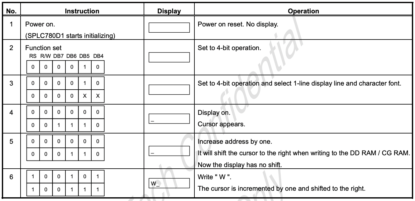
以上圖的 4-bit 初始化流程為範例,雖然有 DB0 - DB7 bit,但由於 4-bit mode 下只會使用到 DB7 - DB4,因此只看 DB7 - DB4 來編寫要輸入的值,同時對照 datasheet 的 instruction table 來理解 DB7 - DB4 各 bit 所代表的意思。
 1void write(uint8_t data);
 2
 3void init()
 4{
 5	//wait for hardware init
 6	wait();
 7	write(0x2); // set to 4-bit operation
 8
 9	write(0x2); // set to 4-bit operation
10	write(0x0); // and select 1-line display line and char font
11
12	write(0x0); // display on
13	write(0xE); // cursor appears
14
15	write(0x0); // increase address by one
16	write(0x6); // shift the cursor to the right
17
18	write(0x5); // write 'W' char (upper 4 bit)
19	write(0x7); // write 'W' char (lower 4 bit)
20}
此外,原先需要用 8 bit(DB0 - DB7)來完成一次動作,不過因為設定成 4-bit 模式,因此需要傳送兩次才能完成一個步驟。
Write Instruction & Write Data
而 DB0 - DB7 的資料還需要搭配正確的 RS 和 R/W 訊號,好讓其值可以傳送到 LCD 模組 IC controller 中對應的 register(instruction register / data register),像是剛剛初始化階段的參數設置就是使用 instruction register,而顯示在 LCD 的字元則是 data register。
同樣以剛剛 4-bit mode 的 code 為例子,將原先的 write function 改寫成能區分 instruction 和 data register。
 1#define SELECT_INSTRUCTION 1
 2#define SELECT_DATA        0
 3
 4void write(uint8_t selector, uint8_t data)
 5{
 6	// Bus represents DB7 - DB0
 7	Bus = ((data<<4) & 0xF0);
 8	RS_pin = selector;
 9	RW_pin = 0; // read = 1, write = 0
10}
11
12void init()
13{
14	//wait for hardware init
15	wait();
16	write(SELECT_INSTRUCTION, 0x2); // set to 4-bit operation
17
18	write(SELECT_INSTRUCTION, 0x2); // set to 4-bit operation
19	write(SELECT_INSTRUCTION, 0x0); // and select 1-line display line and char font
20
21	write(SELECT_INSTRUCTION, 0x0); // display on
22	write(SELECT_INSTRUCTION, 0xE); // cursor appears
23
24	write(SELECT_INSTRUCTION, 0x0); // increase address by one
25	write(SELECT_INSTRUCTION, 0x6); // shift the cursor to the right
26
27	write(SELECT_DATA, 0x5); // write 'W' char (upper 4 bit)
28	write(SELECT_DATA, 0x7); // write 'W' char (lower 4 bit)
29}
Start to Write/Read
最後,我們需要傳送 Start 訊號(E),來告訴 LCD controller 可以開始接收資料和結束接收。參考 datasheet 的 4-bit timing diagram:
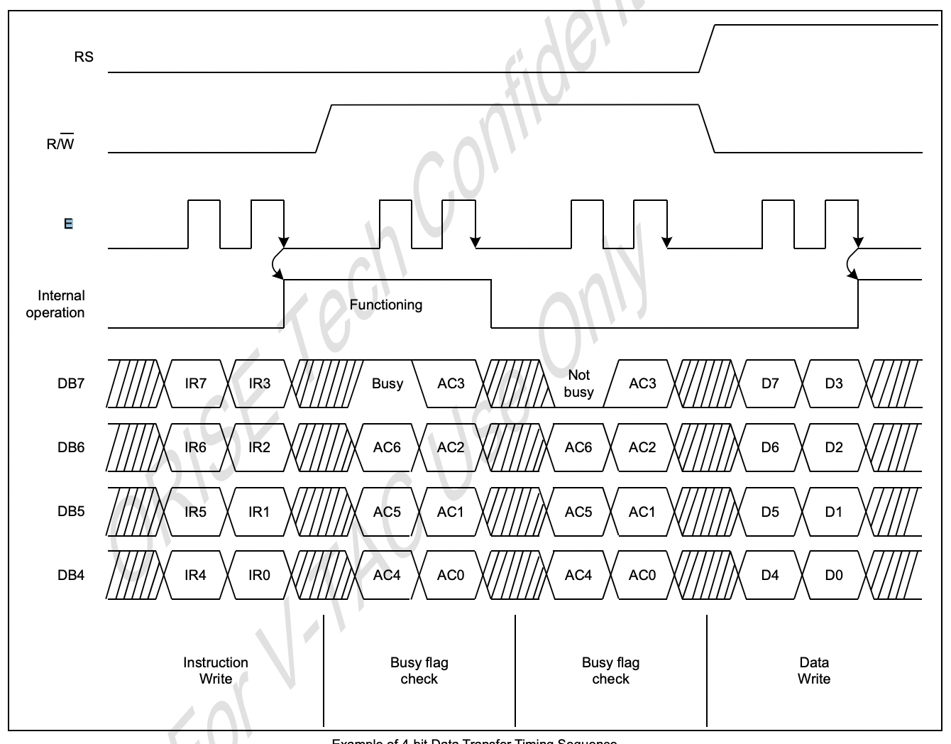
可以看到 E (start signal) 所產生的方波對應到各訊號取值區間,因此我們調整 write function,加入 start signal 來產生方波:
 1void write(uint8_t selector, uint8_t data)
 2{
 3	// Bus represents DB7 - DB0
 4	Bus = ((data<<4) & 0xF0);
 5	RS_pin = selector;
 6	RW_pin = 0; // read = 1, write = 0
 7	E_pin = 1;
 8	delay(600); // delay time should be longer than min required time
 9	E_pin = 0;
10	delay(600);
11}
透過這些訊號控制和資料寫入,我們就可以實現最基本的顯示器控制功能。
I2C LCD adapter
如果直接拿此 LCD 顯示模組連結到開發板,會需要 16 個接腳, 對於接腳數量較少的開發板來說頗不方便,因此市面上就有針對這類型 LCD 顯示模組出了 I2C LCD adapter,只需要 4 個接腳(SDA、SCL、VDD、GND)即可透過 I2C protocol 操作 LCD 8 個訊號腳位。
不過,原始的 LCD 顯示模組需要 16 個接腳,但是 I2C LCD adapter 卻只能支援到 8 個,那麼這樣要怎麼控制 LCD 模組呢?這就用到我們在上述章節所提到的 4-bit interface,以下為 I2C LCD adapter 對應到 LCD 顯示模組的腳位:
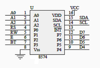
| P0 | P1 | P2 | P3 | P4 | P5 | P6 | P7 |
|---|---|---|---|---|---|---|---|
| RS | RW | E | BT | D4 | D5 | D6 | D7 |
可以看到 adapter 只連接 LCD 模組 D4 - D7 data 腳位,而其他 P0 - P3 腳位則留給 LCD 控制腳位 (RS、R/W、E)所用。這也意味著,如果我們要使用 I2C LCD adapter ,那麼我們勢必得要用 4-bit interface 來操作 LCD 模組。
I2C 相關介紹可以參考:
由於 Rasp Pico SDK 有提供 I2C primitive API ,因此就直接運用此 API 來寫一個新的 write function:
 1#define SELECT_INSTRUCTION 1
 2#define SELECT_DATA        0
 3
 4struct lcd_device
 5{
 6  uint8_t addr;
 7  i2c_inst_t *i2c;
 8};
 9
10static void i2c_write_byte(i2c_inst_t *i2c, uint8_t addr, uint8_t val) {
11	  // primitive I2C API of Pico SDK
12    i2c_write_blocking(i2c, addr, &val, 1, false);
13}
14
15static void lcd_toggle_enable(struct lcd_device *lcd, uint8_t val) {
16    sleep_us(ENABLE_DELAY_US);
17    i2c_write_byte(lcd->i2c, lcd->addr, val | LCD_ENABLE_BIT); // start E pulse
18    sleep_us(ENABLE_DELAY_US);
19    i2c_write_byte(lcd->i2c, lcd->addr, val & ~LCD_ENABLE_BIT); // end E pulse
20    sleep_us(ENABLE_DELAY_US);
21}
22
23static void lcd_send_byte(struct lcd_device *lcd, uint8_t val, int mode) {
24		// we use 4-bit interface to transfer data
25		// so we need to send hight-bit data first
26    uint8_t high = mode | (val & 0xF0) | LCD_BACKLIGHT;
27    uint8_t low = mode | ((val << 4) & 0xF0) | LCD_BACKLIGHT;
28
29    // The data can be sent before or after sending RS and RW signals.
30    // But data should be available before toggling LCD enable pin.
31    i2c_write_byte(high);
32    lcd_toggle_enable(lcd, high);
33
34    i2c_write_byte(low);
35    lcd_toggle_enable(lcd, low);
36}
37
38void lcd_clear(struct lcd_device *lcd) {
39    lcd_send_byte(lcd, LCD_CLEARDISPLAY, SELECT_INSTRUCTION);
40}
假設現在要執行 LCD 模組的 clear display instruction,參考 LCD 模組的 data sheet,我們需要傳送 D7 - D0 為 0000 0001 的 data bit,搭配 RS = 0 (instruction register)。
而因為現在是使用 I2C adapter 來傳送訊號給 LCD 模組,參考剛剛提到的 adapter 腳位對應表格,傳送的資料會變成:
1uint8_t high = 0x0 (RS) | 0x0 (DATA) | 0x8 (BT);
2uint8_t low = 0x0 (RS) | ((0x1 << 4) & 0xF0) (DATA) | 0x8 (BT);
另外一個要注意的點是:
1// The data can be sent before or after sending RS and RW signals.
2// But data should be available before toggling LCD enable pin.
3i2c_write_byte(high);
4lcd_toggle_enable(lcd, high);
之所以傳送資料會需要呼叫兩個 function,主要原因是 data 需要在 E pulse 開始之前就設置好,因此第一個 function 主要目的是傳送 data bit 和 RS bit,第二個 function 則是通知 LCD 可以開始取值。
由於 I2C 通訊時需要知道 I2C bus 的 slave address,因此要先確認 I2C LCD adapter 的 address 位置。可以看 adapter 的 IC controller datasheet 來取得預設 address,例如型號 PCF8574 是 0x27,而 PCF8574A 則是 0x3F。
LCD 2004 Sample code for Rasp Pico
https://github.com/YuShuanHsieh/lcd-2004a-i2c