
Lab 4 包含三個部分,其中 A 部分介紹 x86 架構的 multiprocessor 啟動與初始化流程,並且實作簡易的 round-robin process scheduling。而我認為從 bootstrap processor 啟動並初始化,到透過 bootstrap processor 把其他的 processor 啟動的整個過程相當重要,可以讓新手更具體地知道 multiprocessor 的運作方式。
JOS 實作 intel MultiProcessor Specification(MPS) 標準,在看 source code 的時候,搭配這個文件來看會更加理解每項步驟的用意。
Note: Multiprocessor 架構會依據設計而有所不同,以下所提到的內容皆以 x86 MPS 制定的規格為主。
Multiprocessor
Architecture
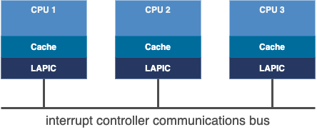
Multiprocessor 架構下,每個 processor 有各自的 L1 cache 和 APIC,並且透過 ICC (interrupt controller communications) bus 進行溝通。
 (MPS設計當時,一個 CPU 是一個 core)
在 MPS 中 processor 被定義成兩種類型:
- bootstrap processor (BSP) BSP 通常由硬體決定,負責執行 BIOS 和 bootloader code 並且啟動作業系統。
- application processor (AP) 於作業系統啟動後,負責執行程式。
MPS 提到 CPU 1 會被指定為 bootstrap processor,負責喚起其他的 application processor,當然這樣的機制會造成一個問題,當 CPU 1 啟動過程中失敗,整個系統都無法運作。(在 bootstrap processor selection architecture in SMP systems 中整理了幾個常見的硬體選擇 bootstrap processor 的方式,並且提出可擴展的選擇機制)
實驗中我們使用 qemu 來執行 JOS kernel,而在 qemu x86 的 SMP 模擬,也是簡單地使用 cpu[0] 來當作 bootstrap processor。
Bootstrap Processor
Bootstrap processor 負責執行部分硬體與作業系統的初始化,首先來複習一下 JOS 從開機到執行 kernel code 所需要的概要流程:
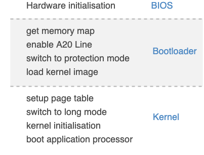
流程中可以看到針對單一 processor 的初始化配置,例如 page table(每個 processor 有各自的 MMU),這也意味著我們在喚起 application processor 時也需要再對每個 AP(application processor) 進行相同的配置,以讓它們能夠正確地執行 code 和 address translation。
另外,我們也注意到當 JOS kernel 的 global variables 都初始化完成後,才會執行 boot application processor,這是因為我們只需要一個 core 去完成 kernel 初始化即可。
Application processor
Read Multiprocessor Info
要喚起 application processor 之前,作業系統需要取得相關的資訊,才能知道系統內有多少 AP 需要喚醒。在 x86 中提供了 MP configuration table,每個 table entry 代表一個 CPU,並提供初始化必要的資訊,包含:APIC (advanced programming interrupt controller) ID、CPU flag (usable / bootstrap) 等。
MP configuration table 是由 BIOS 準備,並放置在 MPS 指定的記憶體區塊內。喚起 AP 前,作業系統會先搜尋特定記憶體位置,判別是否有設置 MP configuration table,再來進行後續配置。不過 MP configuration table 並不是必須的,如果沒有此資訊,就是使用 uniprocessor 的方式來運行,或是採用預設的 configuration 來設定系統 (可以想成有幾組預設的系統模組,因此 BIOS 只需要知道模組 ID 就好,不需要逐一組織各 CPU 的資訊)。
BIOS For a multiprocessor system, the BIOS may perform the following additional functions:
- Pass configuration information to the operating system that identifies all processors and other multiprocessing components of the system.
- Initialize all processors and the rest of the multiprocessing components to a known state.
 1void mp_init(void)
 2{
 3	struct mp *mp;
 4	struct mpconf *conf;
 5	struct mpproc *proc;
 6	uint8_t *p;
 7	unsigned int i;
 8
 9    // default: the first CPU is boot CPU
10	bootcpu = &cpus[0];
11	if ((conf = mpconfig(&mp)) == 0)
12		return;
13	ismp = 1;
14	lapicaddr = conf->lapicaddr;
15
16    // parse mp configuration
17	for (p = conf->entries, i = 0; i < conf->entry; i++) {
18		switch (*p) {
19		case MPPROC:
20			proc = (struct mpproc *)p;
21			if (proc->flags & MPPROC_BOOT) {
22				bootcpu = &cpus[ncpu];
23				cprintf("Found boot cpu..\n");
24			}
25			if (ncpu < NCPU) {
26				cprintf("type: %d apicid:%d version:%d signature:%x feature:%x flags:%x reserved:%x\n", proc->type, proc->apicid, proc->version, proc->signature, proc->feature, proc->flags, proc->reserved);
27				if (proc->flags & MPROC_EN) {
28					cpus[ncpu].cpu_id = ncpu;
29					ncpu++;
30				} else {
31					cprintf("Found unusable CPU. Not intiializing it..\n");
32				}
33			} else {
34				cprintf("SMP: too many CPUs, CPU %d disabled\n",
35					proc->apicid);
36			}
37			p += sizeof(struct mpproc);
38			continue;
39		case MPBUS:
40		case MPIOAPIC:
41		case MPIOINTR:
42		case MPLINTR:
43		p += 8;
44		continue;
45		default:
46			cprintf("mpinit: unknown config type %x\n", *p);
47			ismp = 0;
48			i = conf->entry;
49		}
50	}
Boot application processor
有了 processor 資訊,接下來等到 kernel 初始化完後就可以來喚醒剩下的 application processor。 MPS 規範的喚醒流程為:
- 設置 code entry point 到 warn reset vector
- 發送 INIT IPI 重置 AP 狀態
- 發送 STARTUP IPI 讓 AP 執行指定位置的 code
- 持續 Polling 直到 AP 的狀態改變,確認 AP 初始化完成
其中有幾個重點需注意:
- LAPIC (local advanced programming interrupt controller) 在 disable 狀態下,還是能被動接受特定 IPI (interprocessor interrupt),因此 BSP 才可以透過上述所提及的
INIT和STARTUP來與 AP 溝通。
the AP’s local APICs are passively monitoring the APIC bus and will react only to INIT or STARTUP interprocessor interrupts (IPIs)
- 要注意 AP LAPIC interrupt enable 的時間點,以避免 interrupt 會被發送到還沒有初始化完成的 AP,導致 AP 無法正確的處理 interrupt。(這邊說的比較概念,主要是這取決於 interrupt mode 和如何 route interrupt,因此沒有制式的答案)
Local APIC registers
上述有提到發送 STARTUP IPI 這類的操作,其實就是修改 local APIC register 的值,因此我們需要對照著 local APIC registers 的表格,才能下達正確指令。
另外一點要注意的是,此時 JOS 的 BSP 已設置好 page table 和 enable paging,因此要先將 register 的 physical address 對應到 virtual address,才可以正確操作。
1static void boot_aps(void)
2{
3    // Write entry code to unused memory at MPENTRY_PADDR
4    // KADDR: translate a physical addr to a virtual addr
5    code = KADDR(MPENTRY_PADDR);
6    memmove(code, mpentry_start, mpentry_end - mpentry_start);
7}
接著來觀察 JOS 如何操作 local APIC registers,首先,每個 local APIC registers 為 4 bytes,因此 JOS 透過:
1// Local APIC registers, divided by 4 for use as uint32_t[] indices.
2#define ID      (0x0020/4)   // ID
一次位移 4 bytes 的方式來 access 指定 register 位置。
接著參照 local APIC register 文件來設置對應數值,舉例來說,向特定的 LAPIC 發送 STARTUP IPI command:
1lapicw(ICRHI, apicid << 24);
2// addr >> 12, 12 means the offset of a page
3lapicw(ICRLO, STARTUP | (addr >> 12));
To send an interrupt command one should first write to 0x310, then to 0x300. At 0x310 there is one field at bits 24-27, which is local APIC ID of the target processor.
ICRHI 和 ICRLO 就是指 interrupt command register,根據要求,我們需要先設置 high reigster,其值為 LAPIC ID,再來設置 low reigster。
low reigster 的值 STARTUP | (addr >> 12) 要參考 interrupt command register 表格:
- Bits 0-7 The vector number, or starting page number for SIPIs
- Bits 8-10 The destination mode. 0 is normal, 1 is lowest priority, 2 is SMI, 4 is NMI, 5 can be INIT or INIT level de-assert, 6 is a SIPI.
CPU State Initialization
最後就是初始化 applcation CPU 配置:
1struct CpuInfo {
2    uint8_t cpu_id;                 // Local APIC ID; index into cpus[] below
3    volatile unsigned cpu_status;   // The status of the CPU
4    struct Env *cpu_env;            // The currently-running environment.
5    struct Taskstate cpu_ts;        // Used by x86 to find stack for interrupt
6};
在 multi-processor 架構中,有些資訊是每個 CPU 獨立擁有,像是當前執行的 env (process) 和 kernel stack 等。其中,我們把重點放在 kernel stack,透過各自 CPU 擁有自己的 stack,來確保每個 CPU 能平行執行。
而 stack address 的資訊是放在 task state segment (TSS),TSS descriptor entry 又是放在 global descriptor table (GDT)中。綜合以上內容,我們就可以來實作 trap_init_percpu function:
 1void trap_init_percpu(void)
 2{
 3    uint8_t id =  thiscpu->cpu_id;
 4    // assign stack address
 5    thiscpu->cpu_ts.ts_esp0 = KSTACKTOP - id * (KSTKSIZE + KSTKGAP);
 6
 7    // get TSS from global descriptor table
 8    struct Segdesc *seg = &gdt[(GD_TSS0 >> 3) + 2*id];
 9
10    // assign stack address into TSS
11    SETTSS((struct SystemSegdesc64 *)seg, STS_T64A, (uint64_t) (&thiscpu->cpu_ts),sizeof(struct Taskstate), 0);
12
13    // load TSS selector
14    ltr(GD_TSS0 + 2 * (id << 3));
15
16    // load the IDT
17    lidt(&idt_pd);
18}
透過實驗,可以看到 multi-processor 的啟動結果。
1SMP: CPU 0 found 2 CPU(s)
2enabled interrupts: 1 2
3MP: CPU 1 starting
結論
MultiProcessor Specification(MPS) 從 1994 年正式釋出以來,雖然已經過了很多年,不過從文件中可以看到各個軟體層(BIOS/OS)需要負責的工作,以及更具體地讓作業系統開發者了解 enable multi-processor 的流程,讓使用者了解到 linux kernel 設置 SMP configuration 的意義。